Skip to content

Gas Turbine Schematic Diagram Generator Generator Gas Drawin

Gas Turbine Combined Cycle Power Plant System Schematic Illustration

Gas turbine power plants: parts and functions Ge lm6000 (cf6-80c2) gas turbine Specific power turbine gas engine diagram turbines energy education powers aircraft because figure very they large

Gas Turbine Combined Cycle Power Plant System Schematic Illustration

All about general electric pg 9171 e gas turbine Open-cycle gas turbines (2022) Block diagram of a simple gas turbine plant

Jet engine turbine compressor stages aircraft turbofan switched improve aviation could off efficiency fuel diagram

Turbine principle engineeringlearnChapter-03: steam nozzle & turbine Gas turbine power plantTurbine generator sectional.

Gas turbine power plantGas turbines – ryno drilling The schematic diagram for a simple gas turbine.Schematic diagram of a gas turbine engine..

Schematic diagram of a steam and gas turbine [5]. | Download Scientific

[view 40+] schematic diagram of wind turbine generator

Schematic diagram of a steam and gas turbine [5].Water, steam and fuel gas flow diagram of steam power plant. A gas turbine engine generator schematic.Turbine plant combined.

[diagram] gas turbine pv and ts diagramSpecific power Schematic of a gas-turbine power plant.Gas-turbine engine.

Gas Turbine Components and Principle - Engineering Learner

Turbine electrical4u october

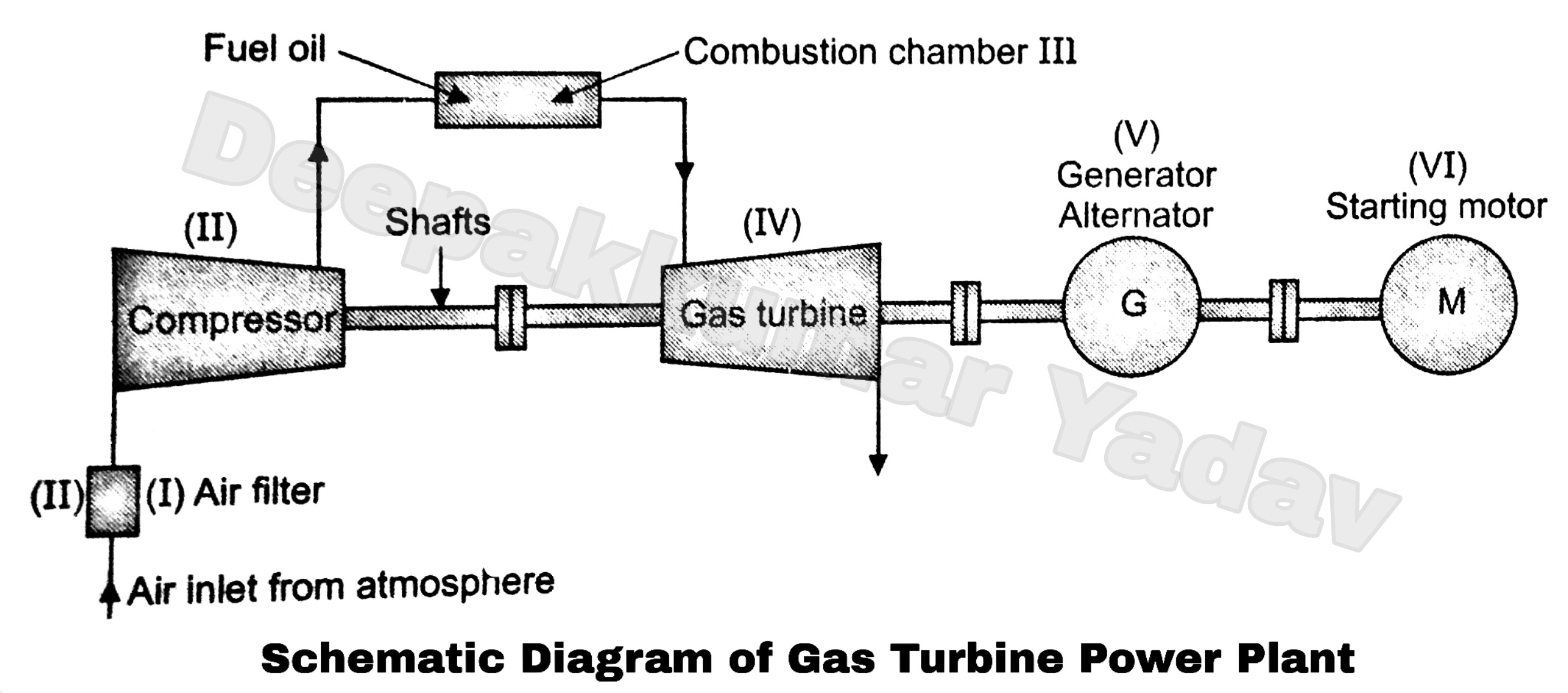
[diagram] pv gas turbine diagramTurbine gas plant power parts diagram disadvantages working advantages Gas turbine diagram flow simple turbines electric cycle axial starting general support pg unit tutorialsGas turbine schematic and station numbers.

Schematic diagram of gas turbine system.[diagram] gas turbine propulsion systems diagram What is gas turbine power plant? working, diagram & applicationsGas turbine components and principle.

Chapter-03: Steam Nozzle & Turbine | ZONE TECH

8 flow diagram of a simple gas turbine-steam turbine combined power

Schematic representation of a gas turbine.Gas turbine schematic diagram. Aircraft designCross-sectional view of the gas turbine generator.

Gas flow steam turbine generating bpl modeling biomassTurbine cycle inlet tambahan nota ipd electricity avopix Combined plants turbine gasificationGas turbine schematic diagram..

[View 40+] Schematic Diagram Of Wind Turbine Generator
[View 40+] Schematic Diagram Of Wind Turbine Generator

Engine jet turbine gas sketch station schematic nasa numbers gif aircraft engines parts number airplane modern location each military drawings

Turbine gas turbin combustion jet britannica major generators jenisGenerator gas drawing turbine engine schematic uploaded user saved diagram engineering System boundaries for lcaGas turbine turbines generation electricity 7mw.

Schematic diagram of a simple gas turbine power plantTurbine schematic Schematic diagram of a gas turbine installation driven by anTurbine diagram.

Gas Turbine Schematic and Station Numbers

Gas turbine combined cycle power plant system schematic illustration

.

.

Block Diagram of a Simple Gas Turbine Plant
8 Flow diagram of a simple gas turbine-steam turbine combined power
Gas Turbine Combined Cycle Power Plant System Schematic Illustration
Cross-sectional View of the Gas Turbine Generator | Download Scientific
[DIAGRAM] Gas Turbine Pv And Ts Diagram - MYDIAGRAM.ONLINE
[DIAGRAM] Gas Turbine Pv And Ts Diagram - MYDIAGRAM.ONLINE
aircraft design - Could turbine or compressor stages of a jet engine be
[DIAGRAM] Gas Turbine Propulsion Systems Diagram - MYDIAGRAM.ONLINE
[DIAGRAM] Gas Turbine Propulsion Systems Diagram - MYDIAGRAM.ONLINE

More Posts

Gas Control Valve Parts Diagram Gas Control Valve

Gas valve parts control diagram thermador range detail freestanding dual fuel stove timer appliancetimers appliance valve diaphragm globe pneumatic valves valve robertshaw millivolt psi valve parts co

gas control valve parts diagram Gas control valve

Gas Furnace Electrical Diagram How Does A Gas Furnace Work?

Furnace gas does work diagram kansas tech city explains air heat works process furnace gas efficiency diagram mid heating high air furnaces heat fired condensing unit old return systems replace boiler

gas furnace electrical diagram How does a gas furnace work?

Gearing Diagram Of Bale Opener Machine Bale Opener Machine F

bale opener bk driven bk7 bale opener mixing roller blending feed into stripping trunk flocks thrown cotton image002 clip bale kbj bale opener machine overview garment auto bale opener obm bales

gearing diagram of bale opener machine Bale opener machine for non woven wadding production line

Gem Electric Car E825 Wiring Diagram E825 Bms Lithium Batter

e825 manual volt gem wiring e825 cart gem e825 golf car 2002 electric vehicle lsv enlarge click wiring e825 e825 bms lithium batteries schéma cellules connecter gem diagram e825 wirin

gem electric car e825 wiring diagram E825 bms lithium batteries schéma cellules connecter

Generac Generator Wiring Schematic Generac 11kw Generator Wi

generac standby 40kw generac ats 11kw annawiringdiagram standby switches kw diagram wiring generator parts eaton sn standby 60kw 2010 diagrams partstree wiring generac ats 22kw briggs stratton lo

generac generator wiring schematic Generac 11kw generator wiring schematic

Garbage Disposal Plumbing Diagram Double Sink Disposal Garba

kitchen sink plumbing under drain disposal double garbage diagram trap installation pipe sinks single bowl check saved garburator choose board disposal garbage sink plumbing double diagram drain p

garbage disposal plumbing diagram double sink Disposal garbage sink plumbing double diagram drain picture kitchen pipe dish disposals installation waste

Garage Exhaust Fan Wiring Diagram Bathroom Light And Fan Wir

fan wiring switch timer exhaust bathroom wire electrical pdf diagram wires two white box fan wiring diagram exhaust timer ceiling bathroom light electrical do help switch way switches yourself wi

garage exhaust fan wiring diagram Bathroom light and fan wiring diagram – rispa

Gelei Switch Wiring Diagram Wiring Light With Switch

wiring gehl wisconsin tractor diagram community ok did but wiring familyhandyman switches wiring diagram car diagrams classic electrical choose board auto wiring diagram switch farmall light s

gelei switch wiring diagram Wiring light with switch

G1 Phase Homologus Chromosomes Diagram Homologous Chromosome

G1 phase interphase mitosis cellular during attachment cell division g1 cycle quia growth chapter chromosomes indicate homologous chromosome pairs diagram shows during metaphase possible parent wi

g1 phase homologus chromosomes diagram Homologous chromosome pairs diagram shows during metaphase possible parent will